|
|
Optimizing Enterprise Network Bandwidth For Security Applications
Improving Performance Using Antaira’s Management Features
In today’s business workplace the internet is becoming more and more relied upon for essential day-to-day activities. The days are gone where web surfing and email were the primary use of the network for a business. Camera monitoring is an essential element in every business; whether they are for inventory scanning, worker safety, loss prevention or general security. In the past cameras used analog signals transmitted on a coax infrastructure. With advancements in image quality, scalability, management features and costs, an increasing number of camera manufactures are switching to IP based cameras. Now, not only is the main network also taking on applications such as voice over IP, Skype, video conferencing, online radio and personal smart phones; but IP based cameras, which can be bandwidth intensive, are also put onto a company’s main network. How does one keep up with this ever expanding, constantly hungry bandwidth monster? A company can purchase more bandwidth and equipment to support it, or increase the efficiency of the network. Antaira Technologies’ industrial networking equipment is able to provide a more efficient architecture for applications that run on the enterprise network, such as security monitoring. Features such as multicasting with IGMP are able to improve the performance of a congested network. Other features, such as redundant rings can ensure that the edge-level of the network stays in operation even if a segment of the network is taken offline or damaged.
Internet Group Management Protocol (IGMP)
The Internet Group Management Protocol (IGMP) can be categorized into three divisions: broadcast, unicast and multicasting.
Broadcast traffic is when data is sent out to all devices on a network. A good example of this would be when a network is using Dynamic Host Configuration Protocol (DHCP). When a computer connects to a local network that uses DHCP the computer will broadcast and request information so that it can properly communicate with the rest of the devices on the network without causing a conflict. The downside of broadcast traffic is that it sends data to everyone on the network, whether they need the data or not. Broadcast traffic also forces computers that do not need the information to dedicate CPU resources to process the broadcast traffic regardless of whether it is intended for them or not.
Unicast network traffic uses point-to-point communication, whereas broadcast traffic sends data out to everyone in a one-to-all scenario. In unicast, with the address of the devices known on the network, information can be sent to a specific individual address.
This allows all the other devices on the network to not have to look at and process information that is not intended for them. Unfortunately, if the information needs to be sent to multiple addresses on the network, the information will need to be sent out separately each time to each address. The more recipients there are, the more times the network will have to transmit the message. A disadvantage of using unicast networking is unicast flooding. Unicast flooding is where, while on the journey to a specific address, the information passes through a switch that does not know where the address of the intended recipient is on the network. The switch will then broadcast the message on all ports in an attempt to get the information to the intended recipient, thus flooding a segment of the network with unneeded information that all recipients need to process.
Multicasting utilizes the best of both broadcast and unicast networking. The broadcast aspect is using a single source address to broadcast information a single time throughout the network. The unicast aspect ensures that that the traffic that is broadcast out onto the network is only received and processed by the intended recipients. This saves bandwidth on the network by reducing the number of transmissions that unicast would need to do. As well as reducing the amount of processing that individual locations CPU’s would needlessly have to do when using broadcasting.
IGMP resides within the IPv4 internet protocol domain and is very efficient in handling multicasting traffic, such as security camera monitoring, within a network. The requirement is that the routers and switches on the network are multicast capable and the video cameras and software support multicasting. IGMP with snooping is able to build a Group Destination Address (GDA) table of destination addresses and pathways to all of the devices on a network. This is done by the IGMP Querier occasionally sending a message to all layer 2 devices, requesting what multicast units or groups of units they are connected to. This way, when layer 2 switches or routers on the network receive information with a GDA, they can either send it to the intended device or drop the information if it is not intended for any devices connected to the switch. This reduces the amount of traffic going through the switches as well as preventing other devices on the network from processing information that is not intended for them.
Multicasting enabled devices are especially important for networks that have security cameras on them. In most networks that have security cameras implemented on them, the security cameras are on the main enterprise network rather than a separate internet service network. Even though there have been great advancements in how cameras are able to process and compress data, they still consume a significant amount of bandwidth. By utilizing multicasting instead of a broadcast traffic network topology, the reduction in switch traffic and workstation CPU usage will be drastically reduced.
Demonstration
In the example below, a small network consisting of a single switch/router combo unit, two computers and two IP based cameras were used. One computer is used as a typical workstation and the other would be the security station computer that monitors the two IP based security cameras. Both of the computers and IP cameras are connected to the switch/router. A packet analyzer was installed on the workstation computer to monitor how much traffic was being processed by the computer. Two separate tests were run, one using a broadcast setup and the other using multicasting. In image 1.0, to the right, shows that none of the IGMP Snooping or Querier options are enabled. The results from the broadcast setup can be seen below in table 1.1. During the test, the packet analyzer captured a 10 second window of traffic going to the workstation computer. During this brief period, on our small network over 8,500 packets of traffic were processed by the workstation computer.
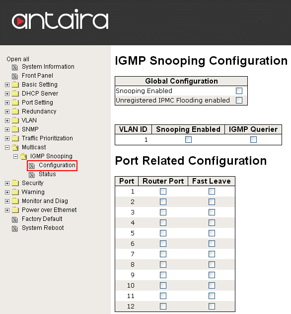
Image 1.0
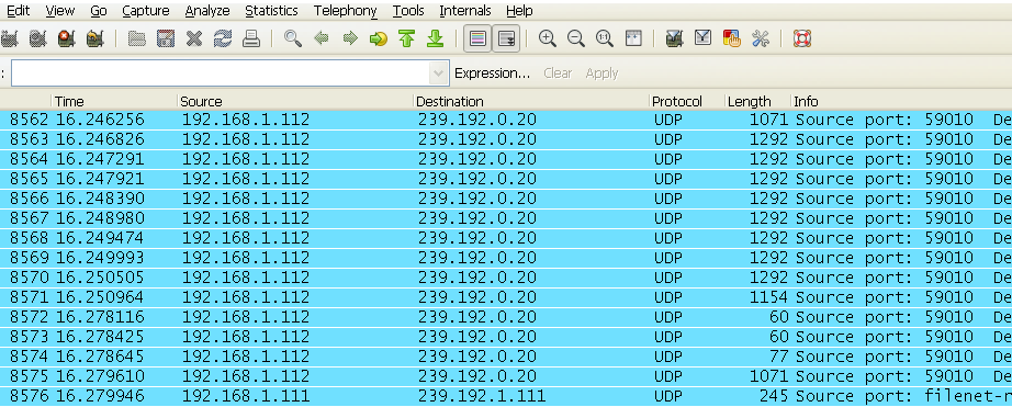
Table 1.1
The vast majority of the traffic received and processed by the workstation was actually intended for the security camera computer.
By enabling the IGMP Snooping and the IGMP Querier options on the switch, as shown below in image 2.0, the network is able to more accurately route traffic between the devices that require the information. In table 2.1, below, shows how much traffic goes to the work station when the IGMP and Snooping features are enabled. 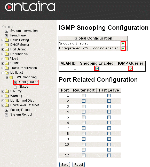
Image 2.0
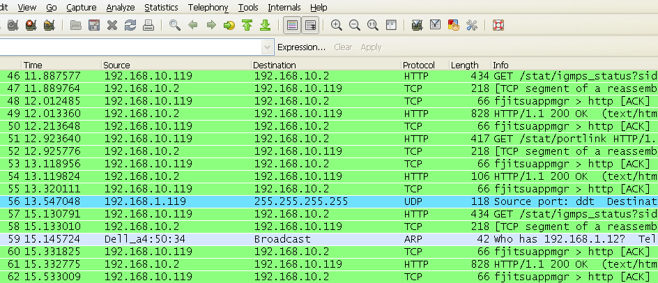
Table 2.1
By enabling just a few options, the packet analyzer on the workstation computer only received 62 packets of information to process during a similar 10 second period. Thus on our small network we had a 99% decrease in traffic to our workstation.
Network Topology and Implementing Rings
Security camera monitoring in the past was typically laid out in either a Star or Tree topology. The Star topology would have all of the data coming back to a central location to be processed. A Tree topology is set up with industrial switches at locations to provide additional connections without having to run additional cables back to the central server for each camera. These topologies were either used because of simplicity, small network size, distance, cost or because unmanaged switches were being utilized. 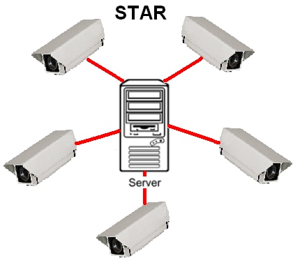 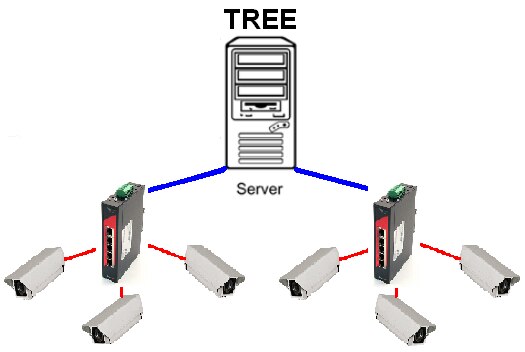
Ring Redundancy Network
On larger networks with more Ethernet switches and industrial wireless routers, using functions such as multicasting will be an effective tool at relieving stress. At this point the user should also consider implementing a ring to ensure that single point of failure will not cripple the infrastructure. Rings help to make a network more manageable and reduce the amount of collisions between points in the network. Rings provide enhanced network performance over traditional bus, star and tree topologies and are capable of creating larger high performance networks. Adding more devices onto the ring does not have a large effect on bandwidth consumption. There are two types of rings used at the edge of a network: a ring and a coupling ring. When using rings, managed switches will need to be used and some setup will be required on each of the industrial switches.
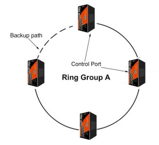
A Ring can be used to connect multiple managed Ethernet switches together throughout the network, providing additional pathways to route data. By look at “Ring Group A” on the right, it shows four switches connected in a ring shape. Typically, the dashed line section labeled “Backup path” is a physical connection that is not being used. If any of the paths or ports used in the ring become damaged or stops working, the damaged section becomes the unused section and the back up path then become part of the main path. The ring functions by occasionally sending a small piece of data called a “Token” around the ring. If the Token completes it journey, then the system knows the ring is not damaged. Multiple security cameras can be placed on one or more nodes of the ring and utilize the enhanced network routing and stability that the ring topology provides. Rings can be used to network multiple floors of a building together on either copper or fiber backbones. Multiple buildings that are a distance apart can be connected utilizing the long distance capabilities of fiber.
A Coupling Ring, as shown below, is used to provide redundant connections with a main and backup path between multiple rings in a network. The coupling ring is the red section in the image. Coupling rings have the same basic operating method as a standard ring. Essentially a ring is formed with a main and backup path between two already existing rings. The ring will occasionally send a small piece of data called a “Token” around the ring. If the Token completes it journey, then the system knows the ring is not damaged. Coupling rings are used in critical applications where a system cannot be immediately stopped for maintenance. A coupling ring is capable of continuing to operate through multiple points of failure, whereas a standard ring can only handle one point of failure. Coupling rings are also used when joining multiple ring locations that are a distance apart or simply splitting a very large ring into smaller more manageable sections. 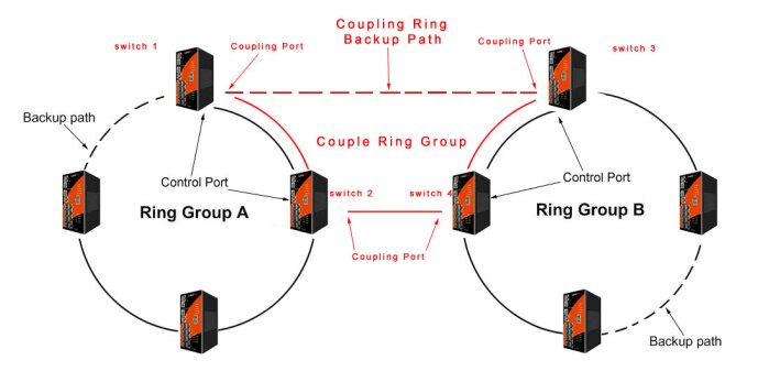
Conclusion
Whatever the application might be, big or small, improving the performance of the current networking infrastructure can be achieved by using IGMP with Snooping. Larger applications are able to achieve enhanced reliability when implementing different ring topologies within the network. Depending on the size and how the network is to be segmented, it can be beneficial to combine multiple types of rings. When multiple industrial switches or rings are involved the effectiveness of the IGMP increases as compared to smaller networks. More industrial switches provide more opportunities for broadcast and unicast traffic to slow the network down with unneeded flooding and retransmissions that can be prevented.
|
|
|
|